Lost Foam Casting Aluminum

I needed a pipe mounting flange for a project, so I decided to make one and get some experience with lost foam casting at the same time. This flange is used to connect a metal plate to a one inch water pipe. I could have bought a flange, but I wanted to try lost foam casting. First thing to do was to design the part. I used Fusion 360 to do the design.

Fusion 360 Flange Image

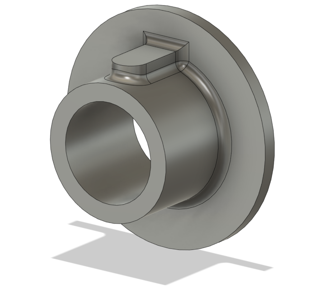
The mounting holes and the set screw hole are not included here as they can’t be cast. The design was converted to G code for my CNC router. The router was used to make a foam pattern of the flange. I used pink construction foam and machined the pattern out of a 4 X 4 X 2 inch block of foam.

Foam Pattern

This is an early attempt at machining the pattern. The mistake I made here was using double sided tape to hold the foam block while being machined. The tape gets milled when cutting the rim of the part. The adhesive on the tape sticks to the foam and tears it. Solution is to only put tape where it does not get milled. A neat thing about lost foam casting is that you don’t need any draft on the pattern.

Patterns With Sprue

To improve the surface finish the foam patterns and the sprue are coated with thinned dry wall compound. In the above image two patterns are attached to the sprue. The coating was first brushed on then the pattern was dipped in the compound. It is important to not have any bubbles in the compound as the bubble will make bumps on the casting. More patterns could be added to the sprue if needed.

Foam Pattern in Sand

The pattern is then buried in a bucket of dry sand with the top of the sprue exposed. Here I have added a pouring basin to funnel the molten metal into the sprue. The pouring basin is made with petrobond an oil bonded casting sand. The molten aluminum is poured into the basin. The metal vaporizes the foam and fills the resulting cavity.

The first time I tried this was a disaster. I used a plastic bucket which would have been all right except I spilled some of the molten metal which melted the bucket. Sand and molten metal ran everywhere.

Foundry Setup

The above image is the setup I use to melt the metal for casting. The furnace is a refractory lined metal bucket. The furnace is started using propane from the larger tank. Once it is heated up the waste motor oil from the smaller tank is turned on. Starting on propane eliminates smoking during warm up. Once it is running on waste motor oil the propane is turned off. A blower in the wooden box supplies air for combustion. In this image the furnace is warmed up and running on waste motor oil.

Finished Casting

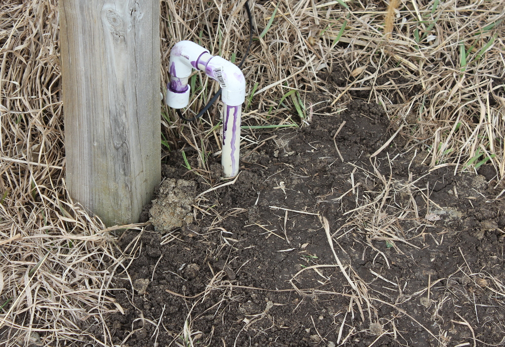
Above is and image of the completed casting. After casting I cut off the sprue and machined the base flat. Then the holed were drilled and tapped. This flange fits nicely on one inch schedule 40 pipe.

Posted in CAD, CNC, DIY, Machine Shop, Metal Working | Tagged , , , , , | Leave a comment

Making Acrylic Domes

This is part of a project to make and improved enclosure for my all sky meteor camera and domes for other instruments that look at the sky. Looking around on the WEB I found some YouTube videos showing making acrylic domes. Most heated just the acrylic sheet and then placed it in the blowing fixture. I did not want to invest in some rapid clamping system so I decided to heat the sheet already mounted in the fixture. This also has the advantage that you don’t have to quite as speedy when inflating the dome.

Baseplate

The base of the fixture is a 12 inch square steel plate 1/4 inch thick. It is fitted with a 1/4 inch NPT pipe and air hose coupler. On the top is and adjustable gauge to control the height of the dome. This should be set to the radius of the dome. The dome is inflated until it almost touches the gauge.

Seal

To seal the acrylic sheet so that it can be inflated a silicone mat is used. These mats are used by crafters as a work surface because glue and paint do not stick and they are heat resistant.

Clamp Ring

I made the clamp ring out of 1/2 inch Baltic birch plywood. I cut a circular hole the size of the dome. The clamp ring also serves as a drilling template to drill the mounting holes in the flange of the dome.

Inflation Hose

The inflation hose attaches to my shop air supply and has a valve to control the air going into the dome. There is no easy way to let air out so you have to be careful to not over inflate the dome.

Inflated Dome

The recommended temperature to heat the plastic is 325F. Oven mitts or welding gloves are needed to handle the fixture when taking it out of the oven. I have a kitchen stove in my shop to use for projects such as this. After removing the heated fixture from the oven the clamps need to be retightened because the plastic softens and everything expands when heated. The dome is slowly inflated until it almost touches the height gauge. If there is a small leak the air has to be carefully adjusted until the plastic cools off enough to become stiff. The hot steel base plate will keep the flange of the dome soft longer so the clamps should not be removed until the base plate is cool to prevent warping of the flange.

First Dome

Here is the first dome I made. It is over inflated. The gauge arm left an impression in the top of the dome and it is not a good hemisphere. It still needs the holes drilled in the flange and the flange trimmed to size.

The dome is part of a larger project to make an improved enclosure for my All Sky Meteor Camera. Expect more articles on the rest of this project.

Posted in Amateur Science, DIY, environmental monotoring, Machine Shop, Uncategorized | Tagged , , | Leave a comment

Smoke Ring Generator

A quick project for the Forth of July.

I saw a video of someone making smoke rings online. The device shot a burning ball of fuel into the air that turned into a vortex of black smoke. Searching the web did not turn up much information on how this worked. I finally found one video that showed one for a science fair project that gave me enough information to figure it out. This video also described the recipe for the fuel a mixture of gasoline, diesel, used motor oil and dish detergent. Basically the fuel needed to be blown into the air from a long vertical pipe and ignited as it exited the tube. The charge of fuel was stored in a U shaped bend at the bottom of the pipe. Compressed air from a tank was used to blow the fuel out of the pipe. My goal was to keep my design as simple as possible. The air tank needed a compressor to fill it and a valve to let the air out. I chose to eliminate all that and use what I call a gas generator to eject the fuel.

The base of the smoke ring generator. The fuel is stored in the U bend. The gas generator is the short length of pipe with the cap on the end. To operate the generator some fuel is poured down the barrel. About one soup can of fuel works well. Then the gas generator is unscrewed and loaded with the proper amount of black powder and a fuse is inserted at the end.

The complete unit.

A propane torch at the top is used to ignite the fuel as it exits the pipe.

Above is the initial blast from the generator before it forms a smoke ring.

There is a video on youtube on the generator in action. https://www.youtube.com/watch?v=d2KmAEdk2gk

Posted in DIY, Pyrotechnics | 1 Comment

All Sky Meteor Camera

A recent addition to my weather station tower is an all sky meteor camera. I purchased this camera from AllSkyCams as a kit. Building the kit saves me a little money and lets me know exactly what I have and how it goes together. The camera consists of 7 camera modules that are arranged to cover the entire sky. The modules use a Sony Starvis sensor that is especially good under low light conditions. 

Above is an image of the parts in the kit for the camera except for the dome. Assembling the kit went well. After that it was necessary to program each camera module with the correct settings and IP addresses. 

Above is an image of the assembled camera without the dome. I have labeled each module with it’s IP address. In the center of the assembly are a custom made Ethernet switch and a power over Ethernet module. 

Above is an image of the completed camera mounted in it’s place on my weather station tower. The dome is painted white on the inside to help keep the camera modules cool in the summer sun. A layer of flat black paint inside the white paint helps reduce internal reflections that cause glare in the images from the camera modules.

The camera is connected to a minicomputer running Linux with a 2TB hard drive. Video from each camera module is recorded 24-7 in both HD and SD. Software running on the minicomputer examines the SD video for meteors. When a meteor is detected a clip is extracted from the video in both SD and HD and saved. Also running on the minicomputer is a web server that allows viewing the recorded video and the meteor clips. 

The image above is a typical meteor trail captured by the camera. Frames from the video clip of the meteor are stacked to make the equivalent of a long exposure image of the meteor trail.

In the image above an entire night of meteor activity has been stacked. This was taken during the recent Geminids meteor shower. The curved lines are star trails and the straight are meteors.

This camera is part of a network with two other cameras belonging to the Cedar Amateur Astronomers. With multiple cameras the trajectory of a meteor can be calculated. 

Links:

https://www.allskycams.com/

https://www.cedar-astronomers.org/

https://www.youtube.com/watch?v=g1O1qZo7mUU A video introduction to the all sky camera network.

Posted in citizen science, Electronics, environmental monotoring, Uncategorized | Tagged , , | 3 Comments

Paper Tube Rolling Machine

An important item to build black powder rocket motors is strong parallel rolled paper tubes. Paper tubes have an number of advantages for rocket motors. They are inexpensive especially if you make them yourself. They are biodegradable and if the motor should burst it does not throw dangerous shrapnel around. I use Elmer’s white glue for the adhesive. Epoxy or polyester resin could be used but the tubes would not be biodegradable.

You can buy some sizes of suitable paper tubes but I thought it would be a fun project to build a machine to make the tubes. David Sleeter in his book “Amateur Rocket Motor Construction” describes a rather complicated and tedious method of hand rolling tubes. I found only a couple of items on the internet about making a machine to roll tubes. None of which I liked. So I took ideas from them and added some of my own ideas to come up with the design. With some of the machines you had to cut the paper to length and then feed it into the machine. I wanted my machine to hold a roll of paper. One design you brush the adhesive on the paper as you rolled it up. Other than being tedious applying the adhesive makes the paper soggy and difficult to roll. In my machine the adhesive is placed as a bead just before the paper is rolled up. The pressure of the rollers squeezes the adhesive in a thin film onto the paper. After the picture below was taken I shortened the springs a bit to increase the pressure on the rollers. This makes the glue film a bit thinner which improves the tube roundness.

For the frame of the machine I made the sides out of 3/4″ MDF and the bottom from 1/2″ plywood. These materials are easy to work with and I had plenty of scraps laying around. There are 3 rollers in the machine. One roller a 3/4″ steel rod supports the roll of paper. A rubber roller applies pressure to the paper as it is wound on the steel roller that determines the inside diameter of the tube. Springs press the rubber roller against the tube roller. The tube roller fits into slots in the sides so that it can be easily taken out to remove the completed paper tube. I found that it is necessary to keep the paper tight as it is rolled up so a rod is held against the paper roll to act as a brake. The ends of the mandrel  are machined to fit 12mm bearings. There is a 11mm hex on one end to work with the crank which has an 11mm socket welded to it. This makes it easy to remove the crank when taking off the completed paper tube. 

In the image above are two tools I made to go with the tube roller. The metal strip helps get the paper started wrapping around the mandrel. Below that is a gage to determine when the tube is the desired size.

The tube on the left is a purchased tube and the one on the was made by my machine.

I posted a short video on YouTube https://www.youtube.com/watch?v=q8Fan9tJDFE showing the tube machine in operation.

Posted in Crafts, DIY, Machine Shop, Pyrotechnics, Uncategorized | 7 Comments

Testing Paint for Solar Heating

An upcoming project has an enclosure for electronics that is exposed to sunlight. I wanted to see if silver or white color paint was better at reducing the solar heating in the enclosure. I picked 5 different spray paints to test along with flat black as a sort of control.

  1. Rust-Oleum flat black enamel (control)
  2. Rust-Oleum Mirror Effect
  3. Krylon Rust Tuff White
  4. Rust-Oleum Silver Chrome
  5. Krylon interior exterior white
  6. Rust-Oleum Pure White Enamel 

To test the paints I painted cardboard 6″X6″ squares  with each paint and stapled the squares to a piece of scrap wood to support them and set the samples out in the noon sun.

I tried measuring the painted surface of each square with an IR thermometer but the emissivity of the mirror effect paint was way different than the others throwing the measurements off. So I measured the back side of each square, since that was plain cardboard. Below are the resulting temperature measurements. 

  1. 107.2
  2. 95.9
  3. 98.7
  4. 102.7
  5. 96.8
  6. 96.4

As expected the black paint had the highest temperature. The mirror effect paint had the lowest temperature. Interestingly the silver chrome was worse that the white paints. This tells me that the type of silver paint is important. Of the white paints the Rust-Oleum Pure White Enamel had the lowest temperature. 

There are some other considerations with the mirror effect paint. It is intended to be used to make a mirror by spraying it on the back of glass or other clear material. It is also not rated for outdoor used.  The enclosure to be painted is made of clear plexiglass where the mirror effect paint on the inside would be more mirror like than on the cardboard. So it would actually be indoors and possibly more reflective than on the cardboard.

Most things you see that are painted to reduce solar heating are painted white so I am inclined to use the Rust-Oleum Pure White Enamel but the mirror effect paint deserves some more experimentation. Now to figure out how to compare it with white when painted on the inside of an enclosure. 


Posted in Amateur Science, Astronomy, environmental monotoring | Tagged , , | 1 Comment

Air Quality Sensor

An air quality sensor (dust sensor) has been on my todo list for a while. There are a number of sensor modules on the market for the DIYer but all that I had seen seemed to not be suited for outdoor use. I saw someone that had a PurpleAir sensor. The specs looked good but it was quite expensive and had to be connected to their cloud network. Looking into it more I found that the actual sensor in the PurpleAir device was a Plantower PMS5003. This sensor is available online for around $40. That is more my speed.

My standard interface for sensors is to use a Teensy 3.2 microcontroller to convert whatever signals the sensor uses into USB serial. The PMS5003 interfaces with 3.3V logic level serial data and a set and reset line. The Teensy turns on the sensor every 5 minutes waits for 30 seconds for the fan to come up to speed takes readings and turns it back off.

 The Teensy is mounted on a piece of perfboard along with the connector for the sensor.  The perfboard is mounted to an aluminum disk that just fits inside a PVC pipe cap.

The sensor is mounted to the other side of the aluminum disk.

The PMS5003 does need to be protected from the elements when used outdoors. In the pictures of the PurpleAir sensor it looks like it is mounted in a PVC pipe cap with the open end facing down. So I went out and bought a 4 inch PVC pipe cap and added an aluminum bar to mount it.

Above on the right is the sensor mounted on my weather station tower along with a number of other sensors.

A USB cable connects the sensor with a computer in the base of the tower. This computer runs a script that sends the data every five minutes to my web server where it is logged in a MySQL database. You can view the plots of the data at the link below.

References:

Sensor Data http://www.ocrslc.net/sensors/dust.php


Posted in Amateur Science, citizen science, Electronics, environmental monotoring, Imbedded Software, Nature, Software | Tagged , , , , , | Leave a comment

Telescope Mount Adapter

The University of Iowa donated the Rigel robotic telescope to the Cedar Amateur Astronomers. Plans are to install this telescope in one of the domes at the observatory. To mount the scope an adapter is needed to connect the scope to the concrete pier in the dome and to raise it to the proper height.

Dr. Scott Bounds designed an adaptor and worked with the University of Iowa Physics Department Machine shop to get it fabricated. The adaptor is made of donated aluminum plate. The bottom plate is 1.75″ thick and the rest of the parts are 5/8″ plate.

Dr. Bounds has been busy with his work at the University and Fred Young and myself wondered if we could help out getting the adapter completed. When we inquired about it we were told that it was complete except for the welding. So I offered to help with the welding. My son Paul does aluminum welding and our recently acquired welded is capable of aluminum welding. The machine shop foreman delivered the adapter parts to my shop. It was then that I learned that they had tried to weld the adapter but were unable to get good welds. This made me a bit nervous. We were thinking that they just did not have the time to do the welding.  They were trying to use a TIG welder. TIG welding is excellent for precision welding but is not really suited for the heavy duty welding needed for this thick material. We have a MIG (wire welder) which is more suited for this type of welding. Our welder is set up for .035″ wire.

Above is the mount as I received it.

To clean up the poor welds I used an angle grinder to remove the welds and disassemble the pieces. I ground off all the old weld so we could start over with clean parts. Essential for good aluminum welds is clean metal. After the parts were ground clean they were wiped down with acetone to remove any potential grease or oil.

We did not know what alloy the parts were made of so I just picked one of the two common welding wire types (4043) and turned the welder up to a fairly high power level.

Due to the thickness of the part we thought the preheating would be necessary. So I arranged to preheat the parts with a fish fry burner.

After making a few welds we noticed that the welds all had a crack running the length of the weld. Clearly something was wrong. The dull look of the welds also indicates gas porosity in the weld.  We finally decided that we were welding too hot. The welds were all ground out to get ready for the next attempt. Along with turning down the power we switched to the other common welding wire (5356) and skipped the preheat.

The changed did the trick and we had a nice shiny weld with no cracks.

Above is the adapter with the bottom welding complete and the top plate clamped on to tack weld in place before flipping the adapter over to weld on the top plate. The welding used 4 pounds of welding wire and about 100 cubic feet of argon.

Above is Paul welding on the adapter.

After the welding was complete I sandblasted the adapter to remove the weld smut and splatter. After a coat of paint it will be ready to return to the University shop for final machining.

References:

Cedar Amateur Astronomers https://www.cedar-astronomers.org/

A short video of Paul welding on the mount. https://youtu.be/0kKoOcM15zw


Posted in Amateur Science, Astronomy, Machine Shop, Metal Working, welding | Tagged , , , | Leave a comment

Biochar Study

This is a  citizen science activity that I spotted on Scistarter. I keep an eye on the citizen science projects on Scistarter and this one interested me. Scistarter lists a lot of citizen science projects.

I had seen a lot of things on the internet about using biochar as a soil amendment but did not pay much attention. When I found this project I did a little more reading about biochar.  Biochar is a fancy name for charcoal. I found that there is a lot of research going on studying various aspects of biochar. From what I can see the main benefit of biochar is carbon sequestering with the added benefit of improving the soil for plant growth.

This project is studying the aging of biochar in the soil under a wide variety of conditions. One way to do this is to get citizen scientists from different areas to bury samples of the biochar. The USDA is doing the research for this project. See link references below for more information on biochar.

After I signed up for the project I received a box with four mesh bags of biochar and instructions for burying them. The bags contain some oak biochar and a temperature data logger. One piece of the biochar was sealed in a plastic bag as a reference. The bags were labeled B07 through B10.

The bags were buried on April 18 2019.

I picked four sites around my place to bury the bags. I tried to pick sites that were as different as possible.


Above is my trailer loaded with the things I needed to bury the bags. Some metal fence posts were used to mark the burial sites.

Above is a Google Earth image with the location of each bag marked.


Above is bag B07 in the hole. This site is at 42° 11.955’N 91° 39.256’W. It is under some very large Tartan Honeysuckle. That honeysuckle is very invasive and I really need to get rid of it. The soil here is quite sandy.

Above is a view of the site for bag B07.

Above is bag B08 in the hole. This site is at 42° 11.934’N 91° 39.310’W. This is an area that stays wet a lot of the time. It is a grassy area that I am trying to get native prairie flowers growing. It will not get mowed this year. I burned off the general area here this spring but this exact spot did not burn because it was too wet.

Above is a view of the site for bag B08. You can see that it is a wet low spot.

Above is bag B09 in the hole. This site is at 42° 11.834’N 91° 39.310’W. This area used to be a horse paddock. I planted some trees here some years ago. A lot of the pine trees I planted died. The hole is next to the stump of one of the pine trees.

Above is a view of the site for bag B09.

Above is bag B10 in the hole. This site is a 42° 11.915’N 91° 39.313’W. This is near my garden and next to my asparagus and rhubarb patch. A lot of stinging nettle growing here also.

Above is a view of the site for bag B10.

In six months the bags will be dug up and sent back to the researcher along with soil samples from the sites.

October 10 2019

The bags were dug up today.


References:

Scistarter https://www.scistarter.org/biochar-soil-aging

USDA ARS https://www.ars.usda.gov/midwest-area/stpaul/swmr/people/kurt-spokas/biochar/

Posted in citizen science, environmental monotoring | Tagged , , | Leave a comment

Soil Temperature Probe

A soil temperature probe has been on my todo list for a while. So I decided to build one now along with a number of other improvements, and repairs to my weather station.

The soil temperature at four inch depth is what is used for agriculture and I added sensors at 1,2 and 3 feet. The deeper sensors are mainly for my own curiosity to see annual variations in soil temperature.

The sensors are Microchip MCP9808 Silicon Temperature Sensors mounted on a little board by Adafruit. These sensors communicate via I²C so they can be all wired in parallel and addressed by a microcontroller. To protect the sensors in the ground they are inside a length of 1/2″ PVC water pipe.

Above is a picture of the sensor string and the length of pipe they will go in. It takes four wires the connect the sensors and some telephone wire is a handy way to connect them along with a RJ11 telephone connector on the end of the wire.

Above is a picture of the completed probe. The sensors are in the longest length of pipe. Then a one foot section  gets the sensors away from the place where the probe comes to the surface. This is to prevent the probe or the opening in the ground caused by the probe from affecting the temperature at the sensor. Another length gets the probe above ground. It also allows the probe to come out of the ground next to a leg of my weather station reducing the chance of damage to the probe from mowing or walking on it. Then a U shaped section gets the opening for the wire pointed down. The wire is sealed with silicone but I wanted to also have it pointed down to prevent rain from pooling on the seal and possibly leaking. I filled the pipe with dry sand to prevent convection currents of the air inside the probe from affecting the sensors.

Here is the probe buried next to my weather tower. Because of the horizontal section of the probe the sensors are over a foot from the tower leg. That should be enough to prevent the leg from affecting the readings.

The probe is connected to a Teensy 3.2 microcontroller. I designed and had made a carrier board for the Teensy it just holds the Teensy and connects it to the RJ11 connector to the probe. In previous projects I mounted the microcontroller on a piece of perf board and hand wired the connections. This is much neater and more reliable. The board is sitting in a plastic case to protect it.

The Teensy reads the data from each of the sensors via the I²C bus. The data is then sent over the USB to a Linux machine (Beaglebone Black) which receives data from all the weather tower sensors and send the data to the MYSQL server on the web.


This is a plot of the first  4 days of logging. Red is the 4″ sensor, Blue is the 12″ sensor, green is the 24″ sensor and black is the 36″ sensor. It was warm the first day then it cooled off. The order of the plots completely reversed. As the ambient air started cooling the soil rather than heating it. The smooth lines in the middle of the plot are where I lost some data while switching web servers. The ripples are probably due to sampling noise in the sensors.  I will add some averaging of he samples to smooth out the plots. I also need to fix the time and date labels to make them more readable.

The soil temperature data is online at: http://www.ocrslc.net/sensors/soiltemp.php

References:

Adafruit https://www.adafruit.com/

Teensy from PJRC https://www.pjrc.com/

Beaglebone black https://beagleboard.org/black

Carrier board made by Seeedstudio Fusion https://www.seeedstudio.com/

My web site http://www.ocrslc.net/

Posted in Electronics, environmental monotoring, Imbedded Software, Software | Tagged , , , , , , , , | 4 Comments